Laser Modulators &
Modulation Systems
Introduction
Conoptics manufactures an extensive line of low voltage electro-optic light
modulators, driver electronics, and associated components to satisfy diverse
requirements. The application dictates which versions of modulator and driver
electronics are to be used and what auxiliary components are needed. This data
sheet presents the characteristics of standard products and their operating
parameters when combined to form functional systems. Laser noise reduction
systems, versions of modulation systems with special feedback electronics, are
described in separate data sheets. In addition to catalog products, Conoptics
also manufactures, on a custom basis, intensity modulation systems with high
frequency capabilities beyond 400 MHz and frequency chirping and FM spectroscopy
modulators out to several GHz.
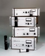
Drive
Electronics
In general, the first application
requirements considered in the choice of modulation system components are the
information bandwidth and waveform requirement. The driver output voltage
achievable is a function of amplifier bandwidth and, while this system parameter
is not isolated from others, such as aperture diameter, operating wavelength,
etc., it is normally the limiting parameter of the system. Standard Conoptics
products include four general purpose drivers:
The Models 10, 25, 50 and 100 are dc coupled broadband amplifiers which require an input of 1 volt p-p into 50 ohms for full rated output. Their bandwidths are a function of the modulator used. Each model requires a different electrical configuration in the associated modulator. The Model 10 requires that the modulator be configured as a lumped capacitor. The Model 25 requires a 100 ohm balanced line; the Model 50, a 50 ohm balanced line; and the Model 100, a two segment (4 port) 50 ohm balanced line.
The Model 302 is primarily intended for low signal bandwidth, long optical wavelength applications. It also offers cost advantages over higher frequency broadband drivers, especially since, due to its high voltage output, shorter capacitive modulators can be used. The bandwidth of the Model 302 ranges from 150 to 200 KHz depending on the modulator used. Input requirement is 4 volts p-p into 50 ohms. All models include a built in manual bias control.
Optical
Modulators
All modulators listed in this data sheet
are of the transverse field type, that is, the electric field produced by the
applied signal voltage is perpendicular to the optical propagation direction.
The voltage swing required by a given modulator at a given operating wavelength
to transit between the full off state to the full on state is called the Half
Wave Voltage (V˝). The transverse field structure allows reduction of V˝ by
manipulation of the crystal length to aperture ratio to a level achievable by
available driver electronics. V˝ is roughly proportional to wavelength and long
wavelength devices usually require higher length to aperture ratios to
accommodate existing driver output levels.
Conoptics offers modulators constructed with three different crystal species: Ammonium Dihydrogen Phosphate (ADP), Potassium Dideuterium Phosphate (KD*P), and Lithium Tantalate (LTA).
Models 370, 380, and 390 utilize ADP as the active element. The unique feature of these models is the virtual non-existence of piezoelectric resonances.
Models belonging to the 360 Series utilize LTA. LTA has the lowest intrinsic V˝ and the longest wavelength IR cutoff. Furthermore, it has a combination of high refractive index and relatively low dielectric constant which allows modulators to be designed which make full use of the intrinsic driver frequency response. Models in the 360 Series exhibit piezoelectric resonances but they are discrete and very narrow.
KD*P is used in Model 350 Series modulators. In terms of optical transmission bandwidth and driver frequency response utilization, this series falls in between ADP and LTA versions.
Modulator
Modifications
Any of the modulators listed here can be used as a phase modulator by simply
rotating the input polarization direction by 45°. This procedure makes one of
the modulator half segments essentially inactive and doubles V˝ (now the
voltage required for a 180° phase shift). A factory modification can be made
during contstruction which restores V˝ to its original value. This modification
precludes use of the device as an intensity modulator, however, and is
irreversible.
Auxiliary
Components
With the exception of 360 Series,
modulators used at wavelengths longer than 2000nm, an integral Glan type
polarizer (analyzer) is supplied with each model listed here. Operation at
longer wavelengths requires polarizers of a different type and may be additional
cost items. Other components such as quarter wave plates used in polarization
rotators, are also available from Conoptics.
The most commonly used auxiliary components are Automatic Bias Controllers (ABC's). The purpose of ABC's is to compensate the long term temperature induced drift of the bias voltage needed to position the applied signal baseline at the desired operating point on the modulator transfer characteristic. Three different versions are available. The first accommodates signal information flows which have a periodic "dead time" such as scanned data or that found in image recorders. Here, a sampling signal is injected by the ABC during the "dead time" and the resulting optical modulation is analyzed to produce an error signal. A feedback loop drives the operating point to the top or bottom of the transfer characteristic, as desired. The second option, used with continuous information flows, such as video disc mastering, samples both the modulated optical output and its reciprocal signal. It averages these samples and produces an error signal which drives the operating point to the midpoint of the transfer characteristic. The third option is similar to the second but is designed to control arbitrary duty cycle digital waveforms.
All ABC versions are available with modulation systems incorporating ADP or KD*P modulators and Model 10, 25, 50 and 100 driver electronics. The inherent stability of 360 Series LTA modulators is sufficient in the majority of applications to avoid the need for an ABC. The addition of an ABC to a modulation system requires integration with both the driver electronics and the optical modulator and is a factory installed option.
Modulation
Systems
The modulators and drivers listed in this data sheet can be used in various
combinations to form high performance, cost effective modulation systems.Table
II shows the key performance characteristics of various combinations of standard
driver electronics and modulators. The high frequency -3dB points may be limited
either by the driver or the modulator. Rise and fall times are normally
calculated as 0.35 divided by the -3dB bandwidth but, due to the compression
caused by the sine squared transfer characteristic over its full on to off range,
the optical rise and fall times of these systems is approximately 20% less.
Table 1 Modulator Specifications:
Note: All cells are 50mm diameter.
Table 2 Modulation Systems:
* Configuration not typical. Call factory for depth
of modulation.
Home | Prodotti | Lista rappresentate | Modulo Informazioni | News | Contatti